Project Description

First fiducial test

Fiducial State Colors
Roaming Bots at MoMath
Rotating Robot
There are some projects that are just so much fun, it is difficult to find a proper place to start with describing them. The robot swarm exhibit we were developing with our partner Three Byte Intermedia in NYC is one of them. So let’s start with the history.
Some two years ago we received a call from Olaaf at Three Byte, inquiring about the possibility of building a swarm of about 100 small robots that could be used to build an interactive museum exhibit that would demonstrate various mathematical concepts, emergent behaviors, and “various other fun things” that the mathematicians would come up with over time. Intrigued by such a challenge, we started thinking about what such a robot had to be able to do.
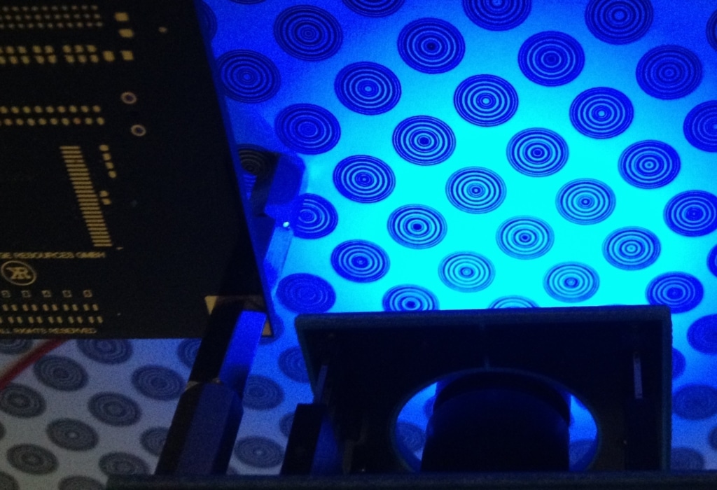
We realized quickly that the key to such a robot design would be the ability of each robot to very accurately know its location and orientation. GPS was not an option since it is too inaccurate and above all, not available in a basement under a Manhattan high rise building. Top-down observation by a camera system was not possible as the robots had to go under a glass floor and people were going to be walking above them. A sensing floor was dismissed since we had very little space underneath to work with and the way we could have reached the required resolution was also not quite clear. Ultrasound or laser ranging to the perimeter was out as there were going to be many other moving robots that would a) interfere as they would use the same method and b) occlude the view as they traveled about. The only feasible approach seemed to be an optical system that could read information that encoded absolute positioning data off the floor. So we did a mock up with one of our FPGA modules and one of our camera peripheral modules to see what kind of resolution and field of view we could achieve with about a one inch distance from the floor.
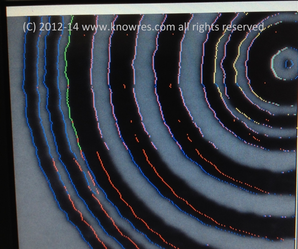
We devised a circular pattern that incorporates a pre-amble, followed by a range of bits that represent an absolute value and a marker bit that identifies the marker as an X or a Y coordinate. The circular pattern allowed us to keep the “image processing” simple enough so that the pattern detection could be limited to operate on one line at a time. Since we only do line processing, no elaborate (and power hungry) frame buffers had to be implemented. A circular pattern also shows the same information twice (once on the way in to the middle and then again on the way out to the opposite edge) so a basic level of error detection was a given as the information is retrieved twice with every successful read. The image on the left shows the color overlay that was generated by the decoding statemachine as it was analyzing the black and white pixel pattern. The full contrast black and white pattern is the result of an intricate image pre-processing stage which compensates for uneven illumination, sets the right exposure and tracks changes in the light levels of the environment. You can clearly see the blue markers for every pre-amble candidate detection, red markers for aborted parsing sequences, green for a possible start of valid data, pink and yellow for edge detects in the data field at wide or narrow pattern features. The visualisation and state color codes were used in the beginning when we were still fine tuning the feature extraction and decoding circuit. The final robots have no more video output or pattern overlay as no human needs to observe its work.
You may think what processor (that is battery powered) can handle a stream of 96Mpixels per second, extract data from that pixel stream, execute motor control commands, drive an LED pattern and handle a communications interface? It is not a traditional processor at all but our KRM-3Z20 module which is based on a Xilinx ARM/FPGA SoC. All the image processing is done in the FPGA section in a custom IP, the ARM core handles protocol parsing and the trigonometric math that allows the bot to translate coordinate reads and line offset data into its absolute position and orientation with sub millimeter accuracy 20 times per second.
To learn more about our modules, please visit the products page. If you have a design challenge that does not fit in a “traditional approach” take a look at our service offering, we’d be happy to assist.

